So let's say you score. You are able to locate historic drawings for your home-- now what? Let us look at a case study. Last month, I published a Saturday Spotlight article featuring a 19th century folk/vernacular home in Roxborough, which had been significantly modified with renovations and a major addition by noted Philadelphia architect Robert Rodes McGoodwin in the mid-1930's. Fortunately, a blueprint copy of drawings for the project has survived and been passed down through the progression of ownership history of the house. The current owner has been kind enough to grant permission for me to share and interpret the blueprints here, so let's do exactly that. A scan of the entire sheet is shown below and includes primarily floor plans and elevations.
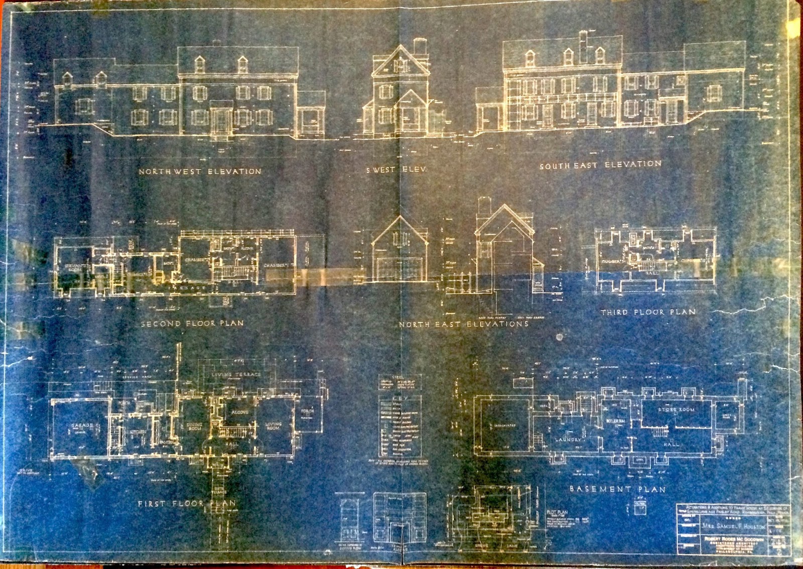 |
| Scan of blueprint copy. Courtesy of the home's owner. |
Provenance
As described, we know that this an authentic copy of the original architectural drawings. That is of no doubt, due to its having remained with the house. In drawing set standards, the title block is essentially what it sounds like-- a block of space on the sheet reserved for basic information including project name/location, the name of the architect or firm, client's name, drawing scale, the drafter's initials, and the title and date of drawing issues and revisions. |
| The drawing sheet title block, providing basic information for the project. At right is a photo of architect Robert Rodes McGoodwin. (Photo source: University of Pennsylvania Archives) |
Title: "Alterations & Additions to Frame House at S.E. Corner of Spring Lane and Paisley Road, Roxborough, Phila., Penna."
Owner: Mrs. Samuel F. Houston
Architect: Robert Rodes McGoodwin, Registered Architect
These pieces specifically tie the drawings to its exact current location. McGoodwin is known to have been commissioned by Samuel Houston for a number of residential properties in Roxborough. As described in the previous article on this home, the Houstons never lived in this home but did own it and alot of land in the neighborhood, commissioning the expanded design of this home as part of a larger effort to bring up the standards of Roxborough at-large. The specification of Houston's wife as the Owner might be an indicator that she may have been more heavily involved in dealing with McGoodwin and his associates for this particular house than her husband was. The original date of the drawing was October 19, 1935 and a revision is noted and dated November 12 of the same year. That November 12 date is likely when the original hand-drafted version of this copy was produced. While there is the possibility that this or some version of this drawing was used for construction, there likely were additional drawings for the builder. I believe that this copy is a final or near-final progress copy used by the architects to communicate the design to the owner, thus its having been passed down through ownership history.
Floor Plans
Most people understand what floor plans are. An architectural floor plan depicts the layout of a building, viewed from overhead, as if one were to take a horizontal slice through it about 4-feet above the floor (in order to show doors, windows, etc). Taking a look here at the first floor plan, I've highlighted a number of standard architectural drawing conventions in yellow. Of course, each room is labeled with its intended use "Kitchen", "Pantry", "Living Room", etc. Primary dimensions of various rooms and of the overall addition are provided. Window tags assign a number to each window, which would typically correspond to a window schedule (not seen in this blueprint), which is a list of all the planned windows with their sizes and other pertinent information. Standard symbols show locations of electrical outlets as well as lighting locations.
A few things to note about the layout itself. McGoodwin's task in 1935 was to design an addition onto an existing house. On the blueprint, I can see the original house comprising the rooms labeled "Living Room", "Alcove", "Dining Room", and "Hall" as this resembles a common arrangement of rooms in many earlier vernacular homes. There are other clues here as well which tells us where the old ends and the new starts. At both the top and bottom of the plan, there is a line cutting through the center of the house labeled "Face of Old Studs". The studs are the vertical wood framing members of the original house. To the right of that line, all the walls are "unhatched", meaning they aren't colored in by the draftsman. This drawing convention in this case indicates all of the existing wood-framed walls. To the left of that line, the walls are "hatched" or "poched" (colored-in solid), indicating new walls built of cinder blocks.
This 1935 addition essentially turned a fairly basic house into an upper class or upper-middle-class residence. The addition is setup as the "servant zone"-- it is more or less an "ell" addition, meaning it is not as wide as the original house and relocates the kitchen function there. The original kitchen may have been where the dining room is now, adjacent to the fireplace. A new garage is added onto the ell addition, and a secondary set of stairs has been added at the kitchen for use by servants to travel to the Laundry Room directly below in the basement and to the servant's bedroom above the garage.
There are a few significant differences between the 1935 layout and the current 2016 floor plan of the house. A powder room is now provided at the 1935 coat closet off of the front Hall; the access to the basement remains with an additional door within the powder room. Today of course there are no servants, no service "wing" of the house, and the house merely functions as a residence for only the family itself. Thus, at some point in the past, there was less need for a separate storage pantry at the kitchen; the wall separating the pantry from the kitchen was removed, giving way to the modern trend of a larger centralized kitchen.
 |
| The current kitchen. At the far wall are two doors to the staircases which once were used by servants, as well as built-ins original to the 1930's addition. This photo is taken standing at a spot which was formerly part of the pantry. The wall between the kitchen and pantry would have been where the oven range currently sits, cutting to the left across the view in the photo. Photo courtesy of The Sivel Group. |
 |
| The current living room. The walls painted in green, and the fireplace, in this photo are all within additions which occurred after the primary c. 1935 renovation. The original exterior wall of the house would have existed approximately at the left edge of the larger built-in shelving, coming out perpendicular and crossing to the back face of the house. Photo courtesy of The Sivel Group. |
 |
| Scan of Second Floor Plan blueprint, courtesy of the home owner. Although the image is stretched a bit, the Bath and Alcove have recently been combined into a larger master bathroom, seen in the following image. |
 |
| Current master bathroom. The wall between the original bathroom and the "alcove" / dressing area used to come across where the vanity exists currently. Door to "Chamber #2" seen in the background. Photo courtesy of The Sivel Group. |
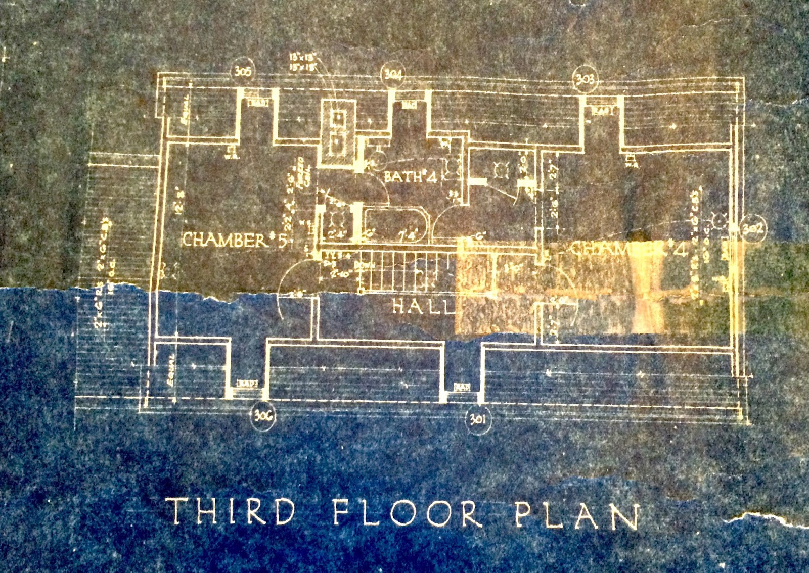 |
| Two more bedrooms on the Third Floor. They're still there, I saw them. Scan of blueprint courtesy of the homeowner. |
Elevations
The term "elevation" in architectural drawing parlance refers to a straight-on view of the exterior facade. On this drawing sheet, we have elevations for all four primary facades of the expanded 1935 house. In this analysis, we will focus on the street-facing (front) facade as well as the backyard (rear) facade.
In the Northwest Elevation above, I have added a few marks in yellow to call out what the architect is conveying with certain drawing conventions. Again, we delineate the extents of the original house as well as those of the 1935 addition. As part of the building's facelift, most of the window openings remained as-is, but some were filled in and others were created new to produce the rhythm McGoodwin sought on the home's exterior. At those new window openings, we see annotation calling out the size of window headers required to span the opening structurally (8"x10", 8"x12"). Also on the elevations we see the basement and foundation construction drawn in lighter, dashed lines, indicating that this construction is below ground level. At the left side of the elevation drawing, each floor level is noted and the floor-to-floor height (vertical dimension between floor levels) is provided. Throughout, building materials are called out with additional annotation: "T&G boards" refers to tongue and groove wood trim; "clapboards" are the horizontal wood siding;"wood lattice" is called out at the side porch area; and on the rear facade of the house, McGoodwin's firm included a "wood and W.I. trellis", W.I. standing for wrought iron. This trellis, as well as the side porch, no longer exist today, so this is a fantastic and accurate depiction of what these features once looked like on the house.
 |
| Blueprint copy of the rear elevation, courtesy of the homeowner. A trellis! |
Capturing a Home's Evolution
This particular house has lived several lives, taking on a new personality on multiple occasions. Originally, in the 19th century, it existed as a relatively simple home with a Folk Victorian style. Then, in the 1930's, a well-known architect crafted an extensive renovation and addition. Without the blueprints which have survived for 80 years, while we might be able to determine this house's evolution, it would have taken much more detective work. Had this home been significantly altered even further after the 1930's addition, these blueprints would have been invaluable in coming close to understanding the house's history at the particular point in its history. These professionally hand-drafted drawings provide insight into the mind of the architect so many years ago, and hopefully now you might be able to interpret more of what you'd find on a set of blueprints if you happen to locate some for your historic house. |
| At left: the rear of the house as it exists today, trellis long gone. Photo courtesy of The Sivel Group. At right: the rear of the house prior to McGoodwin's intervention, pre-trellis. Historical photo courtesy of the home owner. |
No comments:
Post a Comment